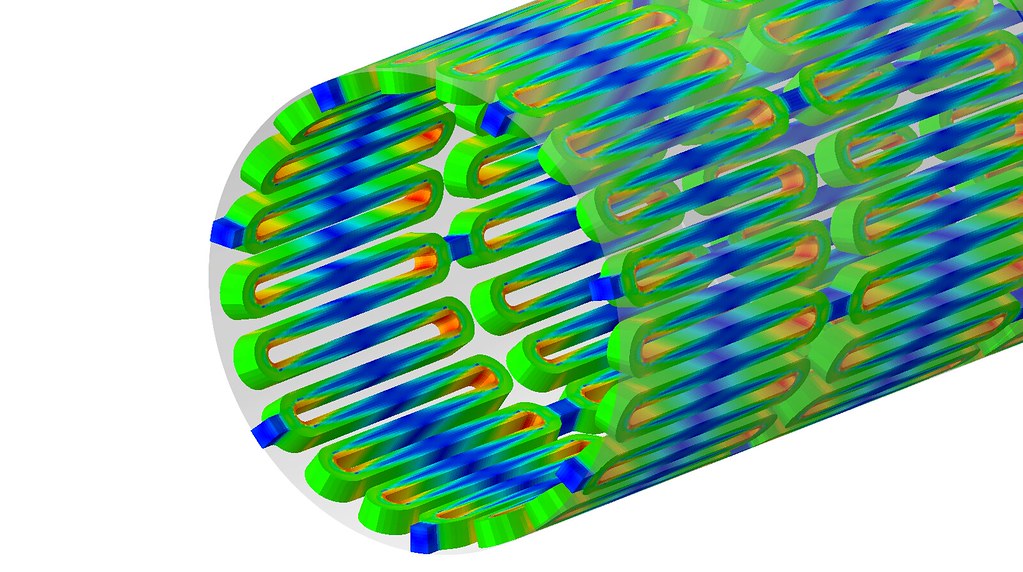
When Ansa is used as Abaqus preprocessor for analysis, the problem of applying bolt pretension is often encountered. In addition to the complex settings, it is also easy to make mistakes, and various problems may occur if you are not careful. The following records the Ansa bolt pretension setting process and some easy mistakes, which will be used as a reference for related analysis later.
1. Solid+Assistant
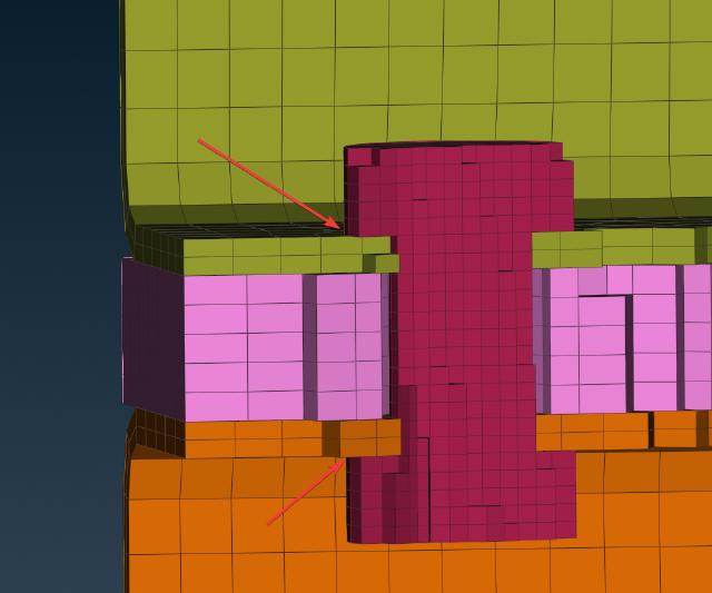
The connection between the solid bolt and the flange surface must be established first. For details, please refer to Abaqus contact settings 。
-
Individual bolts can be set up via the
AUXILIARIES→PRTENS→AssistantAssistant.
-
In the pop-up wizard, select
Surface - Solid ElementsorSurface - Solid Property, then select the bolt entity. Check theDetect and create all possible pretensions.below to automatically search for similar entities and create the same pretension.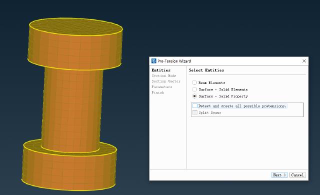
-
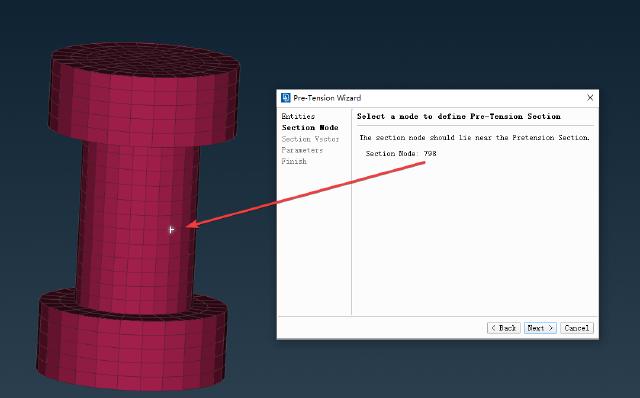
Next, select the first reference point on the bolt body.
-
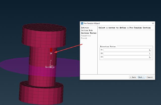
Next, select the second reference point to define the bolt pretension direction. A reference plane will be generated at the first reference point. Note that the pretension direction must be parallel to the bolt axis.
-
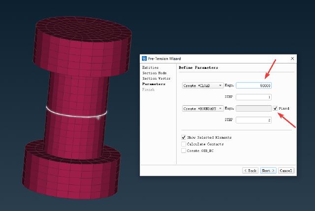
Next, enter the pretension force of 50kN and check the box labeled “Fixed”. Two “STEP"s will be automatically generated. The first “STEP” is used to load the pretension, and the second “STEP” is used to fix the pretension. Other loads can be applied to the second “STEP”.
-
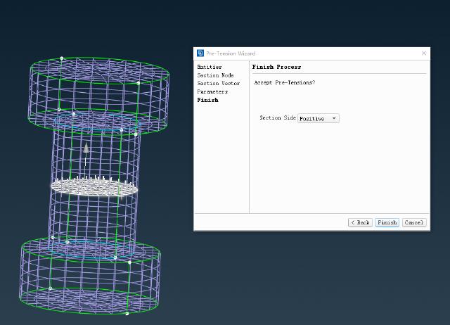
Finally, define the normal direction of the reference plane to confirm the application of the bolt pretension.
After completing the above steps, you can submit the calculation.
Where things can go wrong:
-
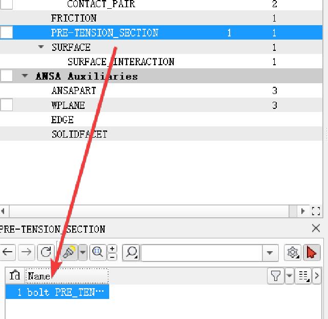
If the non-convergence is caused by contact problems, you can add contact control
Contact Control→Stabilizeto improve the stability of the solution.
-
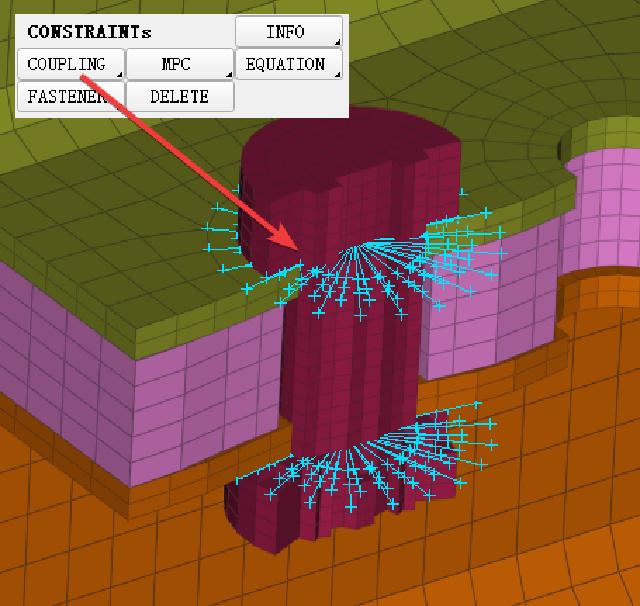
If the system still does not converge after adding contact control, it is recommended to replace the contact between the solid bolt and the flange surface with a Coupling constraint.
-
If the calculation results show that the bolt becomes longer, it is most likely that the normal definition of the reference plane in step 6 is reversed. Simply change the normal direction of the reference plane.
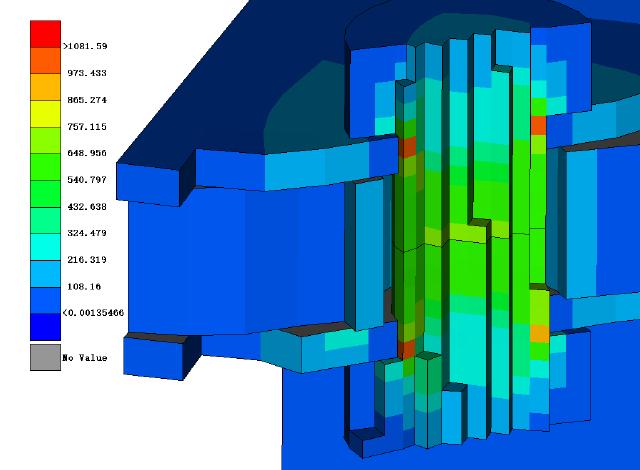
After the calculation is completed, open it through Meta to view the stress distribution state inside the solid bolt.
2. Beam+Assistant
When the problem to be studied does not involve the strength of the bolt body, beam elements can be used to replace the bolt entity, which can reduce the amount of calculation, improve calculation efficiency, and avoid the problem of non-convergence of calculation.
-
For beam elements, you need to create a new beam PID first, define the cross section and material of the bolts, select circular as the cross section, and define the bolt radius.

-
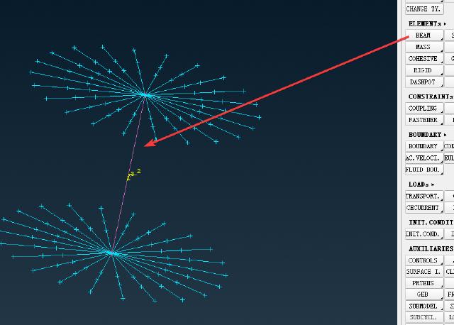
It is necessary to create a new beam unit through Beam (it is recommended to first create two coupling constraints through the bolt holes, and then create a new Beam unit through the center of the coupling constraints), and then assign it to the PID above. At this time, the Beam unit has only one section.
-
Then go to
Meshand split the Beam unit into multiple segments by inserting points throughInsert.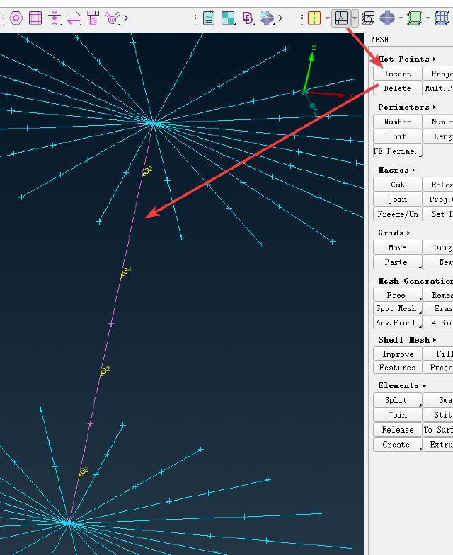
-
Next, start the wizard, select
Beam Elements, and select the middle section of the beam unit. If the beam unit was not split in the previous step, you can select the followingSplit Beams, which will automatically split the beam unit into 3 sections and select the middle section.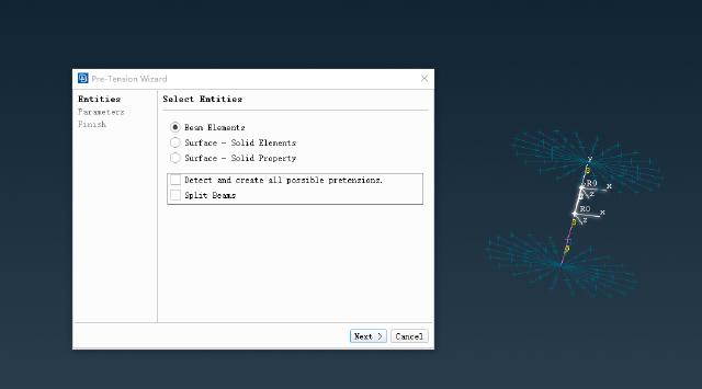
-
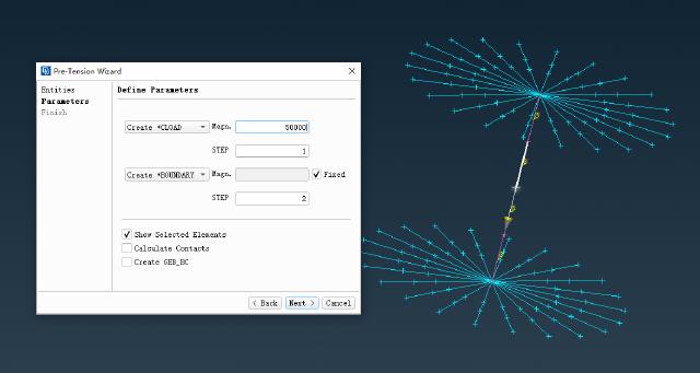
Similarly, enter the pretension force of 50kN and select the fixed pretension state.
-
Confirm creation of pretension.
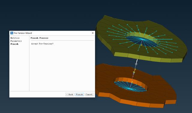
After completing the above steps, you can submit the calculation.
Common Mistakes:
-
Metadoes not support displaying the stress distribution of beam elements. If you want to view the stress distribution of beam elements, you need to useAbaqus Viewerto render the result file. -
You need to turn on
Render beam profilesinView→ODB Display Optionsto display the status of the beam elements.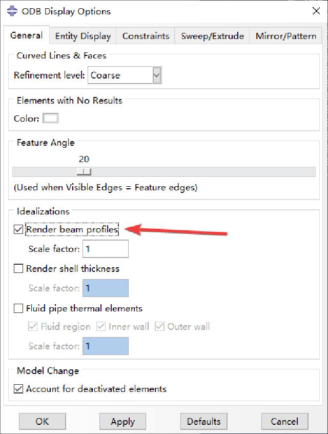
-
To display stresses for beam elements, select
BEAM_STRESS.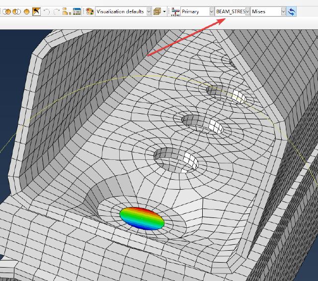
-
If you want to view the stress distribution state of the beam in the results, it is recommended to select the output of all variables in the
*OUTPUTkeyword, so thatBEAM_STRESScan be viewed when rendering withAbaqus Viewer.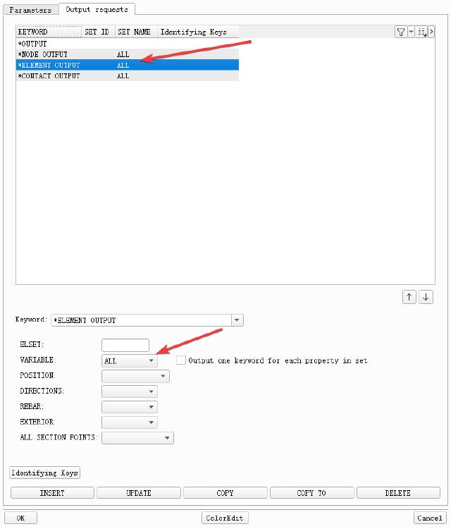
3. Beam+Connection
For connection settings, please refer to Ansa Quick Connection . Bolt pretension can also be set through Connection, which is especially suitable for multiple bolt connections, where models need to be replaced frequently or parameters need to be adjusted. Here, the beam element is selected for the bolt body.
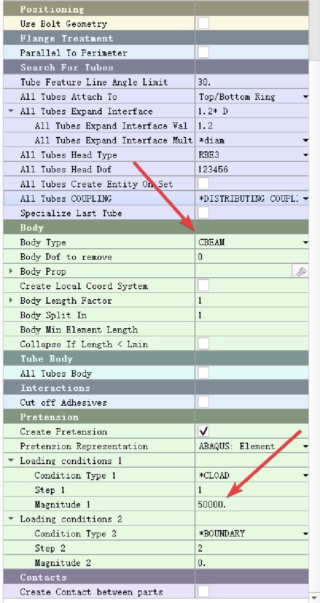
The steps to create PID are the same as step 2 in the previous chapter. Select CBEAM for Body Type, activate Create Pretension and enter the pretension value.
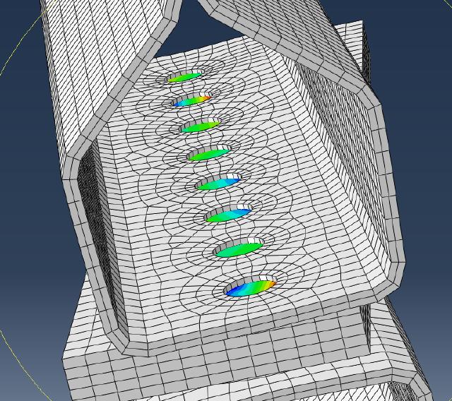
Multiple bolt stress display:
4. Summary
Solid+Assistant: The bolt body stress result is relatively more accurate, but the calculation is large and it is easy to fail to converge.Beam+Assistant: The calculation is small and it is easier to converge, but it can only be used when the bolt body strength is not examined.Beam+Connection: The calculation is small, it is easy to converge, and the change and replacement operations are more convenient. It also cannot directly examine the bolt body strength.
